| Specifications: | |||||||||||||||||||||||||||||||||||||||||||||||||||||||||||||||||||||||||||||||||||||||||||||||||||
| Output | up to 12.7 litres/minute at up to .75bar (2.8 gallons/minute at 11psi) | ||||||||||||||||||||||||||||||||||||||||||||||||||||||||||||||||||||||||||||||||||||||||||||||||||
| Connections | 1/2" (12.7mm) Hose | ||||||||||||||||||||||||||||||||||||||||||||||||||||||||||||||||||||||||||||||||||||||||||||||||||
| Dimensions (L x H) | 142 x 38 mm | ||||||||||||||||||||||||||||||||||||||||||||||||||||||||||||||||||||||||||||||||||||||||||||||||||
| Max. Current | 2.5 A | ||||||||||||||||||||||||||||||||||||||||||||||||||||||||||||||||||||||||||||||||||||||||||||||||||
| Weight | 260 g | ||||||||||||||||||||||||||||||||||||||||||||||||||||||||||||||||||||||||||||||||||||||||||||||||||
Monday, June 14, 2010
inLine bilge pump
Rule make an inline bilge pump: iL200PLUS In-Line & Submersible Pump 12V - the continuous version, can remove net and add a hose. $30 from Amazon

Acrylic domes
There are clear acrylic domes (12" diameter with flange) from calplastics for $55
Thursday, June 10, 2010
Thursday, June 3, 2010
ADC for arduino
From adafruit blog: The analogRead(BANDGAPREF) trick has a lot of problems. I tried it for several applications and found it to be a pain and not very accurate. Here are a few of the things I ran into.
You need to calibrate each Arduino since the bandgap is only specified to be between 1.0 and 1.2 volts on the 168/328. It was only intended for brownout detection. It varies by about 5% on boards I tested which is better than the spec but there is no guarantee.
The value returned when you read it is around 220 so a two bit error results in a 1% error in the value of Vref. When you add zero offset errors in the Arduino ADC and bandgap noise and calibration problems you will likely have fluctuations of 2-3% in your readings.
Putting a cap on the Vref pin helps Vref noise some.
You will likely see the measured level in you tank fluctuate by 2-3% which is not what people expect.
To measure 4-20 ma I use a 100 ohm 0.05% resistor $4.83
http://search.digikey.com/scripts/DkSearch/dksus.dll?Detail&name=MR106-100-.05-ND
and a MCP3422 with an internal 0.05% reference $3.14
http://search.digikey.com/scripts/DkSearch/dksus.dll?Detail&name=MCP3422A0-E/SN-ND
This is all you need to get 0.1 - 0.2 % with no calibration and interchangeable parts.
The beauty of the MCP3422 is that it is a total sigma-delta system with amp, reference, filters, and oscillator so see the adafruit blog post about this useful chip
You just need to make a current vs volume table.
a 12-bit external ADC could be helpful ($28) and also a great thread on noisy numbers on adafruit
You need to calibrate each Arduino since the bandgap is only specified to be between 1.0 and 1.2 volts on the 168/328. It was only intended for brownout detection. It varies by about 5% on boards I tested which is better than the spec but there is no guarantee.
The value returned when you read it is around 220 so a two bit error results in a 1% error in the value of Vref. When you add zero offset errors in the Arduino ADC and bandgap noise and calibration problems you will likely have fluctuations of 2-3% in your readings.
Putting a cap on the Vref pin helps Vref noise some.
You will likely see the measured level in you tank fluctuate by 2-3% which is not what people expect.
To measure 4-20 ma I use a 100 ohm 0.05% resistor $4.83
http://search.digikey.com/scripts/DkSearch/dksus.dll?Detail&name=MR106-100-.05-ND
and a MCP3422 with an internal 0.05% reference $3.14
http://search.digikey.com/scripts/DkSearch/dksus.dll?Detail&name=MCP3422A0-E/SN-ND
This is all you need to get 0.1 - 0.2 % with no calibration and interchangeable parts.
The beauty of the MCP3422 is that it is a total sigma-delta system with amp, reference, filters, and oscillator so see the adafruit blog post about this useful chip
You just need to make a current vs volume table.
a 12-bit external ADC could be helpful ($28) and also a great thread on noisy numbers on adafruit
Depth measurement in seawater
The Cornell sub group shows a depth sensor board provides real-time information about the craft's depth below the surface of the pool. Analog pressure data (up to 100 PSI, or approximately 55 meters below the surface) is obtained from an MSI UltraStable-300 pressure transducer, operating in a 4-20 mA current loop. A 24-bit AD7791 Sigma-Delta Analog to Digital Converter is used to capture pressure data, which is converted into a depth reading by an on-board microcontroller and reported over RS232. $100 from digi-key. Also a microstrain meter to show position
Also see http://www.paroscientific.com/depthsensors.htm for other depth sensors
and Woods Hole Deep Submergence Lab
Also see http://www.paroscientific.com/depthsensors.htm for other depth sensors
and Woods Hole Deep Submergence Lab
Tuesday, May 4, 2010
Adafruit motor shield
ladyada says....motor driver chips that come with the kit are designed to provide up to 600 mA per motor, with 1.2A peak current. Note that once you head towards 1A you'll probably want to put a heatsink on the motor driver, otherwise you will get thermal failure, possibly burning out the chip.
What pins are not used on the motor shield?
All 6 analog input pins are available. They can also be used as digital pins (pins #14 thru 19)
Digital pin 2, and 13 are not used.
The following pins are in use only if the DC/Stepper noted is in use:
Digital pin 11: DC Motor #1 / Stepper #1 (activation/speed control)
Digital pin 3: DC Motor #2 / Stepper #1 (activation/speed control)
Digital pin 5: DC Motor #3 / Stepper #2 (activation/speed control)
Digital pin 6: DC Motor #4 / Stepper #2 (activation/speed control)
The following pins are in use if any DC/steppers are used
Digital pin 4, 7, 8 and 12 are used to drive the DC/Stepper motors via the 74HC595 serial-to-parallel latch
The following pins are used only if that particular servo is in use:
Digitals pin 9: Servo #1 control
Digital pin 10: Servo #2 control
Digital pin 2, and 13 are not used.
The following pins are in use only if the DC/Stepper noted is in use:
Digital pin 11: DC Motor #1 / Stepper #1 (activation/speed control)
Digital pin 3: DC Motor #2 / Stepper #1 (activation/speed control)
Digital pin 5: DC Motor #3 / Stepper #2 (activation/speed control)
Digital pin 6: DC Motor #4 / Stepper #2 (activation/speed control)
The following pins are in use if any DC/steppers are used
Digital pin 4, 7, 8 and 12 are used to drive the DC/Stepper motors via the 74HC595 serial-to-parallel latch
The following pins are used only if that particular servo is in use:
Digitals pin 9: Servo #1 control
Digital pin 10: Servo #2 control
Motor control
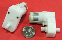
Built the adafruit Motor shield, and now its time to control a motor. I am using a Solarbotics GM2, and as Pololu says...This 224:1 gearmotor (gearbox with motor) is a great low-cost alternative to modified hobby servos or Tamiya gearboxes. The low-current motor is a perfect match for our qik 2s9v1 dual serial motor controller, and the compact size of 2.17" x 1.89" x 0.906" (55 x 48 x 23 mm) makes this unit an attractive choice for small robot designs.

At 5 V, the gearbox and motor provide 50 oz-in of torque and 38 RPM, which is slightly slower than a servo. The free-running current is 52 mA, and the stall current is 600 mA. A built-in safety clutch engages at approximately 60 oz-in.
This gearmotor comes pre-assembled, with the gears fully enclosed. There are built-in mounting holes, and the output shaft is 7mm in diameter with two sides flattened.
At 5 V, the gearbox and motor provide 50 oz-in of torque and 38 RPM, which is slightly slower than a servo. The free-running current is 52 mA, and the stall current is 600 mA. A built-in safety clutch engages at approximately 60 oz-in.
This gearmotor comes pre-assembled, with the gears fully enclosed. There are built-in mounting holes, and the output shaft is 7mm in diameter with two sides flattened.
Subscribe to:
Posts (Atom)