Showing posts with label motors. Show all posts

Sunday, November 21, 2010

DC motor control with 556 timer


Using a 556 timer chip, control of a DC motor using PWM works well - this from the pages of MAKE: 23. Used to drive a Solarbotics gearbox motor, also excellent for changing timing delays and with 2 pots can adjust interval and also duration of pulses.
I used this to press the shutter button on a hacked Canon A70 camera for a timelapse camera.

Saturday, October 30, 2010

XY axes

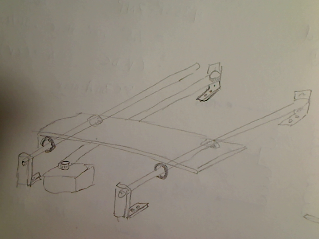
Making an XY axis bot requires two stepper motors, and then either 2 belts or 2 rods.  Been used many times before in CNC machines and 3-D printers:
including
Makerbot
RepRap


Nice tutorial on constructing Y-axis and also idler pulley assembly from Makerbot

Stepper motors

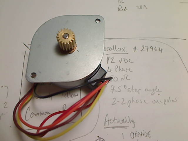
Parallax #27964

Unipolar, 12VDC, 7.5o step angle.  Wiring is
1. Orange
2. Yellow
3. Black
4.Brown
COM Red


Using the adafruit stepper motor shield, with a bipolar stepper from an HP scanner, there was a bad smell, little crack, and I think I just fried half of the shield.  Well only the first blown chip so far, so not bad.

Tuesday, May 4, 2010

Adafruit motor shield

ladyada says....motor driver chips that come with the kit are designed to provide up to 600 mA per motor, with 1.2A peak current. Note that once you head towards 1A you'll probably want to put a heatsink on the motor driver, otherwise you will get thermal failure, possibly burning out the chip.

What pins are not used on the motor shield?
All 6 analog input pins are available. They can also be used as digital pins (pins #14 thru 19)

Digital pin 2, and 13 are not used.

The following pins are in use only if the DC/Stepper noted is in use:
Digital pin 11: DC Motor #1 / Stepper #1 (activation/speed control)
Digital pin 3: DC Motor #2 / Stepper #1 (activation/speed control)
Digital pin 5: DC Motor #3 / Stepper #2 (activation/speed control)
Digital pin 6: DC Motor #4 / Stepper #2 (activation/speed control)

The following pins are in use if any DC/steppers are used
Digital pin 4, 7, 8 and 12 are used to drive the DC/Stepper motors via the 74HC595 serial-to-parallel latch

The following pins are used only if that particular servo is in use:
Digitals pin 9: Servo #1 control
Digital pin 10: Servo #2 control

Motor control

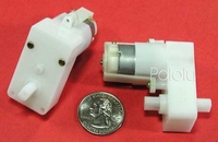
Built the adafruit Motor shield, and now its time to control a motor.  I am using a Solarbotics GM2, and as Pololu says...This 224:1 gearmotor (gearbox with motor) is a great low-cost alternative to modified hobby servos or Tamiya gearboxes. The low-current motor is a perfect match for our qik 2s9v1 dual serial motor controller, and the compact size of 2.17" x 1.89" x 0.906" (55 x 48 x 23 mm) makes this unit an attractive choice for small robot designs.


At 5 V, the gearbox and motor provide 50 oz-in of torque and 38 RPM, which is slightly slower than a servo. The free-running current is 52 mA, and the stall current is 600 mA. A built-in safety clutch engages at approximately 60 oz-in.

This gearmotor comes pre-assembled, with the gears fully enclosed. There are built-in mounting holes, and the output shaft is 7mm in diameter with two sides flattened.